ESP Relays – what a journey 22 August 2021
Posted by David Wilson in General.add a comment
Trying to get some sort of control over this device has been not as straight forward as it should be. Others are going to encounter the same challenges that I did, you’ll come across the same web articles and fall into the same traps of confusion that I did. Below are my discoveries and learnings – with the resulting outcome being success, successful Home Assistant, and HomeKit integration along with the development of a brand new iPhone application that anyone can use (after release via the AppStore) to control the device.
If you’re on this journey too – good luck and I hope you find this useful.
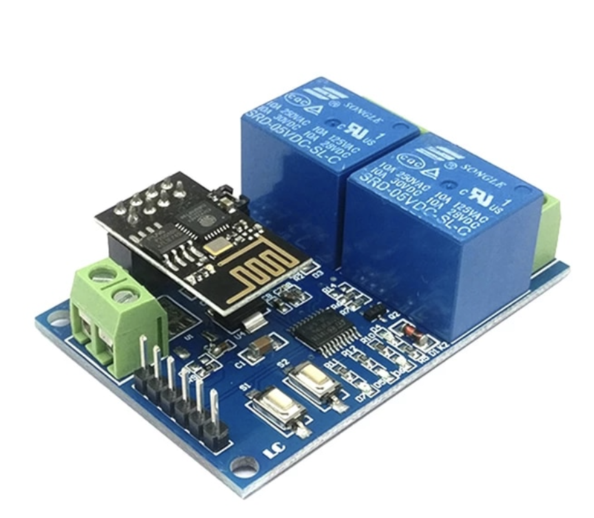
Here’s the device. 5V WIFI Relay Module ESP8266 IOT APP 2 Channel Remote Control For The Smart Home Phone Mobile Dual WiFi Automation Card Module.
https://www.aliexpress.com/item/33044184434.html?spm=a2g0s.9042311.0.0.27424c4daMLDlH
I’ve connected to the header pins using a USB to UART CP2102. – ESP32 CAM Module Support USB 2.0 To TTL UART Module 5v 3.3v CP2102 Aluminum Shell 5Pin Serial Converter STC Replace FT232RL
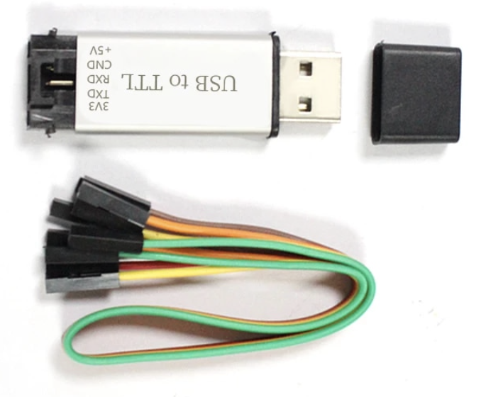
https://www.aliexpress.com/item/1005001947183190.html?spm=a2g0s.9042311.0.0.27424c4daMLDlH
Drivers for various Operating systems (if not built in) are available from here:
https://www.silabs.com/developers/usb-to-uart-bridge-vcp-drivers
I’m using macOS and iPhone – that shouldn’t be a problem. Though all web articles that show how to connect and use these things are Windows and Android. This is a link to a good example.
https://www.hackster.io/makerrelay/esp8266-wifi-5v-1-channel-relay-delay-module-iot-smart-home-e8a437
or the article below this product:
http://www.icstation.com/esp8266-wifi-channel-relay-module-smart-home-remote-control-switch-android-phone-control-transmission-distance-100m-p-12592.html
And this article:
https://manuals.plus/lc/lc-5v-2-channel-wifi-relay-module-esp01-manual
Importantly the first web article talks about different modes of the device and device configuration can be altered using AT commands. Here is the link to the AT Command reference manual:
https://www.espressif.com/sites/default/files/documentation/4a-esp8266_at_instruction_set_en.pdf
More information and downloads can be found here:
https://www.espressif.com/en/support/download/at?keys=&field_type_tid%5B%5D=14
Back to the Mac – I’m using a program from the App Store called Serial.
https://apps.apple.com/nz/app/serial/id877615577?mt=12
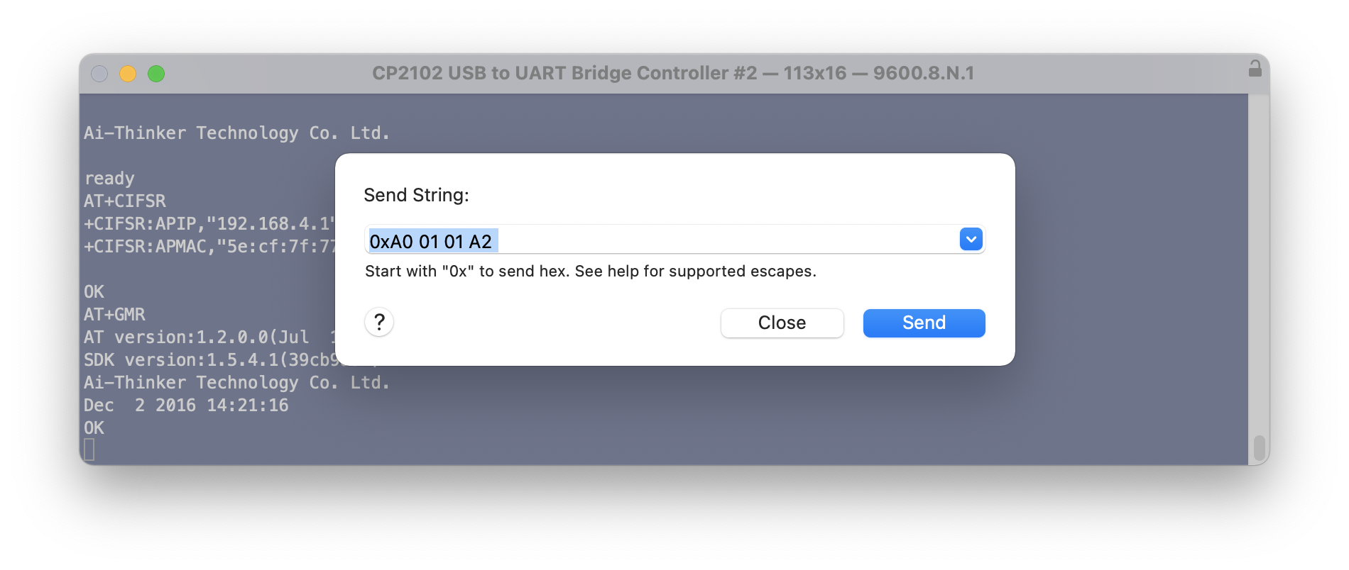
Ultimately we’re trying to send the following hex commands to the chip on the box (not the ESP) to control the relays.
Relay control command (must be hex format):
Open the first relay: A0 01 01 A2
Close the first Relay: A0 01 00 A1
Open the second relay: A0 02 01 A3
Close the second Relay: A0 02 00 A2
Open the third relay: A0 03 01 A4
Close the third Relay: A0 03 00 A3
Open the fourth relay: A0 04 01 A5
Close the fourth Relay: A0 04 00 A4
Taking a look at my stumbling journey… the key thing to remember is that any serial conversation is with the ESP01 running the AT Command set and that the ESP01 should be be passing through the hex control codes to the onboard chip for relay control. This is dependant on the position of jumpers on the board – my shipped in the default position of tx to tx1 jumped and rx to rx1 jumped. For my testing nothing was connected to the relays (they were not controlling anything).
Success: mostly
From the USB to TTL UART the following connections have been made to the header pins on the relay board:
GND to GND
TXD to RX
RXD to TX
And I had 5V supplied by a desk power supply to the power header.
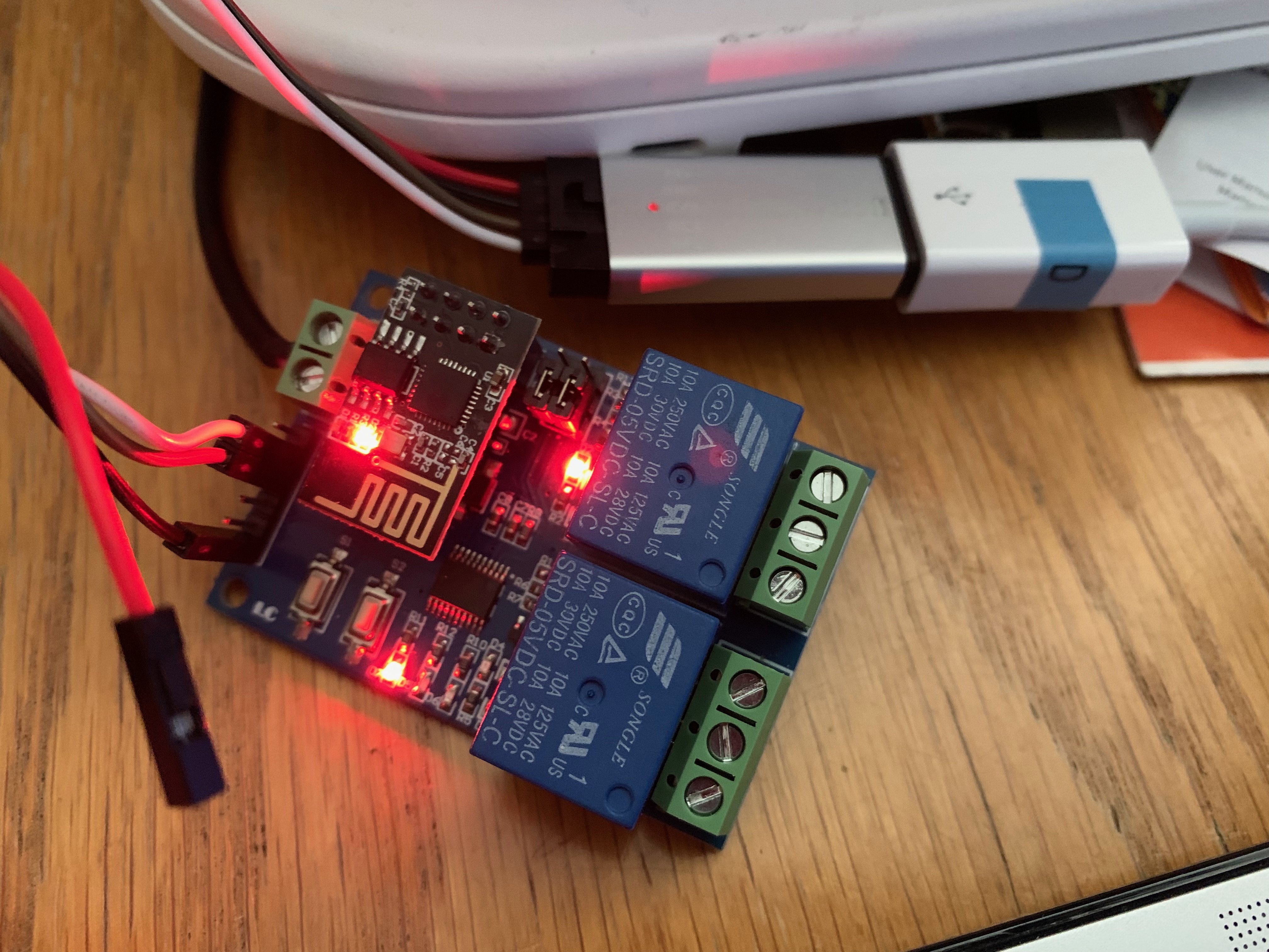
All going well when connected to the computer and you power it on a response will be emitted. And you can type in AT commands and get a response. On initial startup your baud rate will likely be 115200, 8, N, 1.
At this stage I should be able to send a hex string to the device over the terminal to get it to open/close a relay. But it doesn’t work.
Switching the Rx and Tx wires around (just at the board end), and changing the terminal settings to 115200 baud, and power cycling the device – I can send the hex control codes to open and close the relays. But the AT commands no longer work.
Now, lets do something interesting:
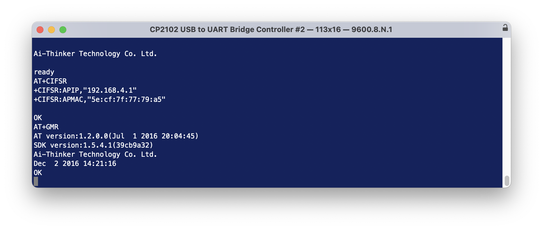
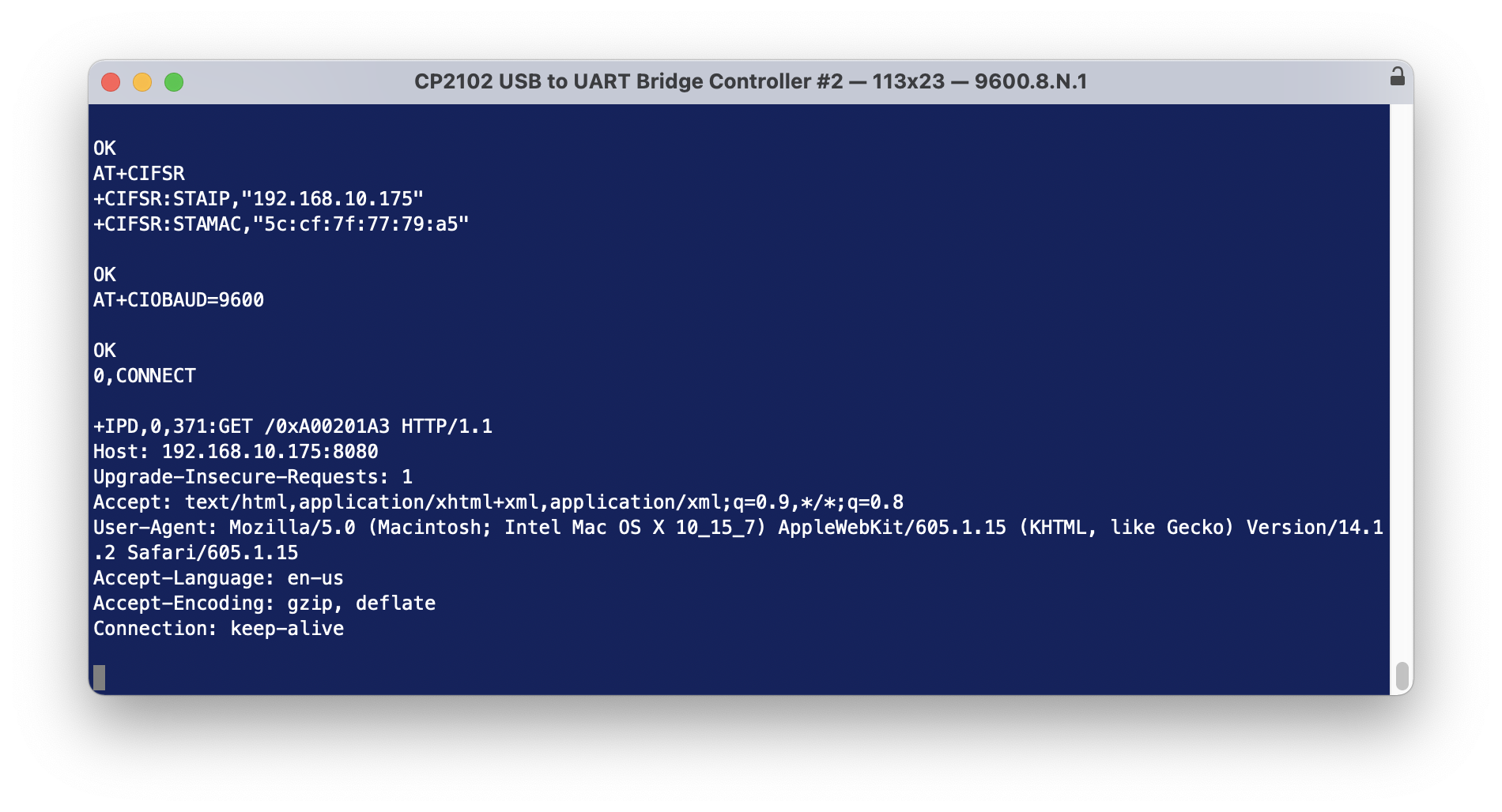
Send the following AT commands (line at a time). The CWJAP line should be altered to be your WiFI network name and password. The AT+CIFSR will emit a response telling your the connected IP addresses and device mac address.
AT+CWMODE=1
AT+RST
AT+CWJAP=“IOT WiFi”,”cryptic01″
AT+CIPMUX=1
AT+CIPSERVER=1,8080
AT+CIFSR
AT+CIOBAUD=9600
Next, from a web browser on the same network, try this…
http://192.168.10.175:8080/xA00201A3
it’s not going to actually do anything because it’s not valid, though we will see some action and it proves we can communicate with the ESP01 – when you sent the web request – you should see the blue light on the ESP01 flash for a moment.
So… simple. All we need to be able to do now is actually send the open/close sequence in some way such that it can be recognised by the ESP01 and passed through to the onboard chip.
Using a Mac App called Hex Fiend I created separate files that contains only the hex sequence for Open (relay 1) and Close (relay 1)
Then using terminal send those files to the device. There was activity by the device but it isn’t good enough to open or close the relay.
nc 192.168.10.175 8080 < relay1open.bin
These work too.
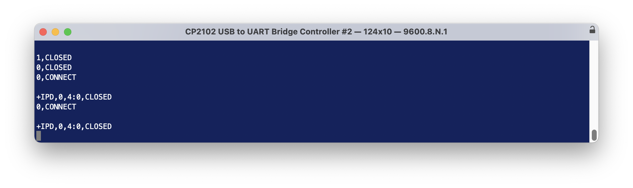
echo -n -e “xA0x01x01xA2” | nc 192.168.10.175 8080
echo -n -e “xA0x01x00xA1” | nc 192.168.10.175 8080
echo -n -e “xA0x01x01xA2” | nc -v 192.168.10.175 8080
0,CONNECT
+IPD,0,4:0,CLOSED
If at this point the relays do not switch on/off when you are sending these commands, respecify the Baud rate … modern boards appear to operate quite happily on 115200, while perhaps the older boards had to be at 9600.
Time for some extra good news if you’re an iPhone user. I’ve written an iPhone application that allows you to send Hex commands to a specified IP address:port. Testing is going really well and I’ll see if I can get it released into the AppStore. I also hope to release the source on GitHub.
-

- pastedgraphic 16
-

- pastedgraphic 17
The other thing I found is if you power cycle the device, some configuration needs to be reset.
I need to find out how to make this permanent.
AT+CIOBAUD=115200
AT+CIPMUX=1
AT+CIPSERVER=1,8080
Home Assistant Integration
If you are running Home Assistant then you’ll want to edit your configuration.yaml file to include this
switch:
– platform: command_line
# scan_interval: 10
switches:
relay1:
command_on: echo -n -e “xA0x01x01xA2” | nc -v 192.168.10.175 8080
command_off: echo -n -e “xA0x01x00xA1” | nc -v 192.168.10.175 8080
friendly_name: Relay 1
relay2:
command_on: echo -n -e “xA0x02x01xA3” | nc -v 192.168.10.175 8080
command_off: echo -n -e “xA0x02x00xA2” | nc -v 192.168.10.175 8080
friendly_name: Relay 2
Update and restart Home Assistant.
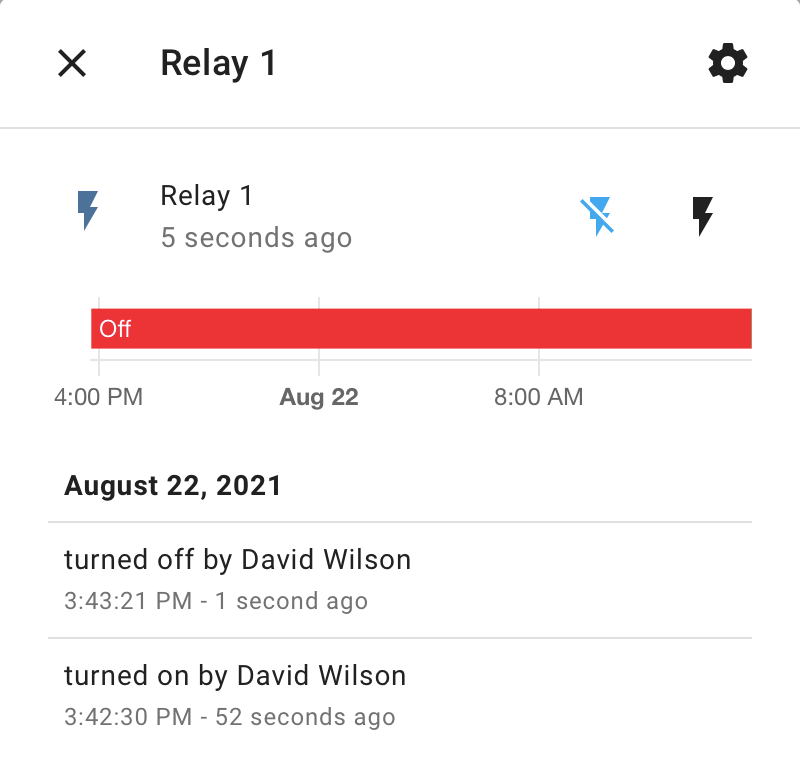
The relays turn up under Entities as shown below
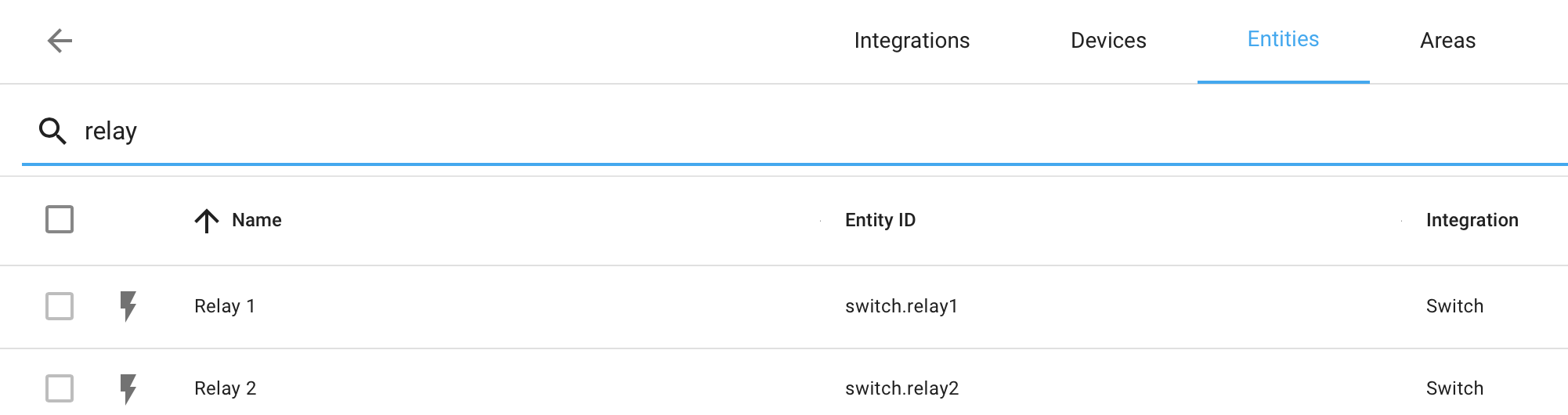
Selecting one brings up this screen where you can click the lightening bolts to send the on/off command sequences.
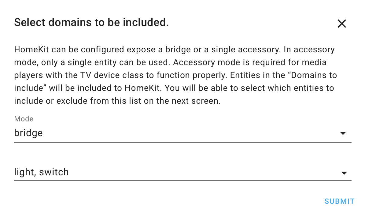
If you also have the HASS Bridge installed for HomeKit integration, you need to check that the configuration will send through details of switches. That way your switches will automatically turn up in HomeKit.
HomeKit integration!
See Home Assistant integration – that needs to work first.
Or buy a relay board that already has HomeKit integration and it will just work – out of the box.
https://www.aliexpress.com/item/1005002668732508.html?spm=a2g0s.9042311.0.0.27424c4d2qKTPZ
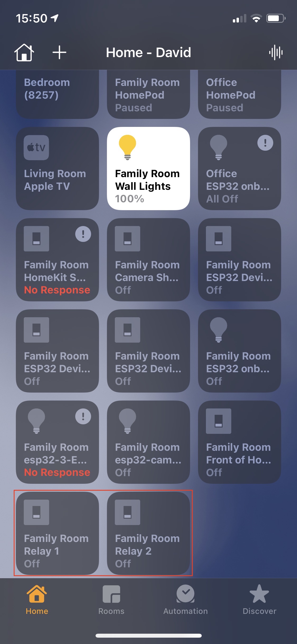
My homekit screen below will look a bit messy … letting the switches come through the HASS brough more than I wanted. I’ve highlighted below with a red rectangle the switches that came through that I wanted.
Finally… Here are details of another board that I found that uses the same Hex sequences for opening/closing the relays. It also says “Status inquiry: FF” – although with my boards I have not got this to work. http://www.chinalctech.com/cpzx/32.html
David Wilson
https://dgwilson.wordpress.com
https://nz.linkedin.com/in/dgwilson65

